적합한 LiFePO4 배터리를 선택하는 데 도움이 필요하신가요?
용도, 전압, 용량, 배터리 크기, 수량, 브랜딩 요구 사항을 보내주세요. BYingPower가 프로젝트를 검토하여 골프 카트, RV, 해양 시스템, 태양열 저장, 지게차 또는 납산 교체에 적합한 LiFePO4 배터리 솔루션을 추천해 드립니다.

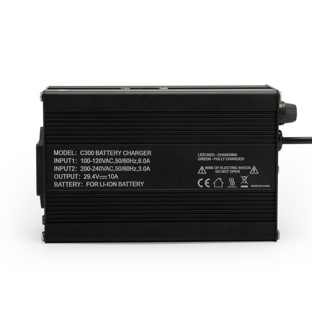
How CAN-controlled and standalone CC/CV lithium chargers differ in control authority, failure behavior, and integration data, plus what to specify before an RFQ.
A CAN-controlled lithium charger takes its voltage limit, current request, and start/stop permission from the battery’s BMS over a data link. A standalone constant-voltage charger runs a fixed constant-current/constant-voltage (CC/CV) profile and knows only what appears at its output terminals. For forklift OEMs, dealers, and fleet buyers, that difference affects charge-termination safety, state-of-charge (SOC) accuracy, spare-part strategy, and who owns the warranty risk when a charge fails. Neither option is automatically better. This guide explains how each architecture works, where each one breaks down, and which specifications to lock down before you request a quote for a battery-and-charger system.
A CAN-controlled charger receives charging instructions from the BMS as digital messages and adjusts its output accordingly. A standalone charger applies a fixed voltage and current profile set in the charger itself, with no digital conversation with the pack.
The word “constant-voltage” needs a small correction. Almost every lithium charger in this category is CC/CV. It limits current until the pack reaches a voltage setpoint, then holds that voltage while the current tapers. “Standalone” describes the control method, not the charging curve. In practice, buyers meet three architectures:
| 차원 | Standalone, fixed profile | Standalone + BMS enable | CAN-controlled |
|---|---|---|---|
| Voltage limit set by | Charger setpoint only | Charger setpoint only | BMS request, within charger hardware limits |
| 충전 전류 | Fixed by charger rating or trim | Fixed by charger rating or trim | Can be reduced on request (temperature, balancing, derating) |
| Who can stop charging | Only the BMS contactor/relay, or the charger at taper end | BMS through enable wire or relay | BMS through a message, plus any hardware cut-off |
| Awareness of pack condition | 없음 | Binary: allowed or not allowed | Voltage, temperature, SOC, fault status (profile-dependent) |
| Effect of a lost link | 해당 없음 | A broken enable wire normally means no charge if wired fail-safe | Depends on the timeout logic that the OEM and supplier define |
| Replacement-market flexibility | High, if the setpoint matches the pack | 중간 | Low unless protocol, bitrate, and IDs match |
| Integration data required | Setpoint, current, connector | Setpoint, current, connector, enable logic | All of the above plus protocol documentation |
| 주요 위험 | Wrong setpoint; unbalanced pack; abrupt BMS cut-off under load | Enable logic that fails open instead of closed | Protocol mismatch; undefined behavior on message timeout |
The table is a qualitative comparison. Actual behavior depends on the charger model, BMS firmware, and the written interface specification.
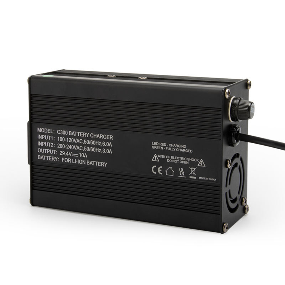
A standalone charger cannot protect the pack by itself. It can only deliver a voltage ceiling, so the BMS has to do the stopping.
Li-Ion BMS’s white paper on charger control states that, at a minimum, the BMS must be able to turn the charger on and off, and that current control is optional. It describes three ways to do this: a signal wire or CAN bit to the charger, a relay at the charger’s AC input, or a relay at the charger’s DC output. The paper ranks the DC-output relay as the weakest option. Opening it while the charger is delivering full power can leave some chargers in an over-voltage fault, cause bursts of electromagnetic interference, or damage the charger. Closing it against a 0 V charger output can weld the contacts through inrush current.
The same paper makes a second point that matters for standalone designs. If the charger’s CV setpoint equals the maximum cell voltage multiplied by the number of cells in series, a top-balanced pack stays protected even when the BMS cannot shut the charger down, because current decays toward zero as the pack fills. The paper adds that this does not protect an unbalanced pack.
For a 16-series LiFePO₄ pack, the arithmetic looks like this: 16 cells at 3.2 V nominal give 51.2 V nominal, and the charge setpoint sits near the cell maximum multiplied by 16. Suppliers commonly quote about 58.4 V for this configuration, but the pack datasheet, not a generic figure, must set the value.
The weak spots of standalone charging are predictable:
None of these problems is fatal. They are the reasons a standalone design needs a fail-safe enable path and a verified setpoint.
In CAN-controlled charging, the BMS transmits what the charger may do, and the charger obeys within its own hardware limits. The conversation typically carries pack voltage, requested current, temperature, SOC, and status, along with charger-enable and fault information.
Two real-world models show the range.
Proprietary protocols. Yale’s lithium forklift documentation says its BMS communicates with the charger over CAN to adjust charge current and keep cells inside their safe operating zone. The same page states that the system uses a custom CAN protocol and that only recommended chargers can currently be used with those batteries. That is a clear example of how a CAN link can lock a battery to a specific charger family.
Standardized profiles. 그리고 CiA 419 device profile for battery chargers defines a CANopen interface so chargers can work with battery modules built to the CiA 418 profile. It specifies that a charger needs, at minimum, the battery type, capacity, number of cells, maximum permissible charge current, and battery temperature. Optional receive messages cover battery voltage, current requests, and SOC. Heartbeat support is mandatory for the charger. A CAN in Automation article on industrial chargers describes a Delta-Q charger family that follows CiA 419, with a galvanically isolated CAN interface and optional J1939 support.
“Supports CAN” is not a compatibility statement. A charger and a BMS must agree on the higher-layer protocol (CANopen, J1939, or a proprietary scheme), bitrate, identifiers or node IDs, message timing, and behavior when messages stop. CoreSpark’s guide on what OEMs must give a forklift battery supplier for CAN integration lists the charging items a supplier needs: charger IDs, voltage and current requests, charger-enable logic, derating, charge termination, and timeout behavior.
Decide in writing whether the BMS, the charger, or the truck controller has the final say. On a standalone charger, authority sits with the BMS through the enable path. On a CAN system, the truck may also gate charging based on key position, parking brake, connector detection, or warehouse rules. When two controllers can both stop or start a charge, the interface document must say which one wins.
The truck’s voltage class is not the charger setpoint. A “48V” forklift can use a 51.2 V nominal LiFePO₄ pack, and the controller, charger, and BMS thresholds all have to agree. Buyers should read the truck plate, the old battery label, and the charger label together, as CoreSpark’s guide to 리튬 배터리를 주문하기 전에 지게차 명판을 확인하기 recommends, because no single label gives every value. For standalone chargers, ask for the exact CV setpoint, the current limit, and the taper-end behavior. For CAN chargers, ask for the maximum voltage and current the charger will accept from a BMS request.
A single-shift truck charged overnight places modest demands on a charger. A multi-shift fleet using opportunity charging puts more stress on thermal limits, taper behavior, and balancing time. A CAN link lets the BMS reduce current when cells are hot or cold, or when balancing needs a low current. A fixed-profile charger can only offer all or nothing. Cold-climate sites should also confirm what happens below the BMS low-temperature charge limit. A pack may refuse charging until it warms or is heated, and a charger with no data link cannot tell the operator why current is not flowing.
On a closed OEM platform, CAN-controlled charging is often the natural fit because the BMS, charger, display, and truck are specified together. In replacement markets, the old charger is the unknown. CoreSpark’s LiFePO₄ charger compatibility guide for replacement markets points out that legacy lead-acid chargers may apply equalization, desulfation pulses, or long float stages that confuse a lithium BMS, so a matched lithium charger belongs in the kit.
Illustrative scenario (hypothetical, not a customer case): A dealer sells 51.2 V LiFePO₄ retrofit packs into a mixed fleet of trucks from several brands. Offering one standalone lithium charger model per pack voltage, each with a BMS enable lead, simplifies stocking and training. Selling a CAN charger for every truck would require a verified protocol match per model. The dealer has to weigh that stocking convenience against the missing current-reduction and status data.
For CAN systems, define the timeout: how long the charger waits for a valid BMS message, what it does next (stop, reduce to a safe current, or hold), and how it restarts. For standalone systems, confirm the enable circuit is fail-safe, meaning open means no charge. Communication faults are a common fault family on forklift lithium packs. CoreSpark’s guide to 지게차 리튬 배터리 오류 코드 notes that communication faults can stem from wiring, termination, bitrate, identifier, wake-up, or firmware problems and can result in charger inhibit. A procurement spec that never asks about this behavior leaves it undefined.
No. CAN gives finer control, but finer control is not the same as lower risk. A CAN charger adds dependencies that a standalone charger does not have: a protocol that must match exactly, firmware versions to track, a cable harness, and a timeout behavior that someone must define and test. If the specification is vague, a CAN system can fail in ways that a simple fixed-profile charger would not.
A defensible position is this: safety should not depend on a message alone. Whatever the control method, the pack should keep an independent protection layer, such as BMS cut-off hardware and a fail-safe enable, so a lost frame or a wrong byte cannot leave the pack charging beyond its limits.
Conditions matter:
The trade-off is flexibility versus data. Standalone designs tolerate more charger sourcing options. CAN designs deliver more information but demand tighter configuration control.
| 시나리오 | Typically better fit | What to verify first |
|---|---|---|
| OEM-integrated lithium truck with display and charge status | CAN-controlled | DBC or EDS file, charger IDs, timeout behavior |
| Opportunity charging across several shifts | CAN-controlled | Current-derating logic, thermal limits, charger duty rating |
| Single-model replacement pack, fixed charger supplied in kit | Standalone with BMS enable, or CAN if the truck needs it | CV setpoint, enable wiring, connector polarity |
| Mixed legacy fleet with unknown chargers | Matched lithium charger supplied with the pack | Old charger label; equalization and pulse modes disabled |
| Cold-climate site | Either, with heating and temperature logic confirmed | Low-temperature charge limit, pack heating, charger behavior |
The table is a qualitative guide, not a rule set. A project’s controller, charger, and BMS documentation always override it.
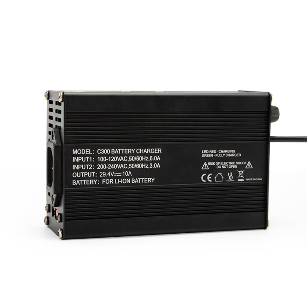
Most charger problems show up first as SOC or charge-completion complaints rather than obvious faults.
| 증상 | Likely area | First check |
|---|---|---|
| Charger will not start | Enable signal, CAN wake-up, node ID, or heartbeat | Enable wiring state, CAN traffic, charger status LEDs or codes |
| Charger shows complete, but BMS SOC is below 100% | Full-charge condition not reached by the BMS | Taper current, cell thresholds, timers, charge-complete flag |
| Charging repeatedly stops and restarts | Cell imbalance or enable chatter | Cell-voltage spread, BMS balancing status, enable logic |
| Communication fault after charger replacement | Bitrate, IDs, termination, or protocol version | CAN bitrate, frame IDs, termination, firmware list |
| No charge in cold conditions | BMS low-temperature charge protection | Cell temperature, heater function, BMS charge permission |
CoreSpark의 SOC gauge calibration and CAN checks guide makes a point buyers often miss: a charger saying “complete” does not prove the BMS recognized a full charge, and a mismatched charger can stop before the BMS sets its full-charge flag. When that happens, the SOC estimator never gets the correction event it needs, and the dashboard drifts.
Give the supplier the whole charging environment, not just the pack’s voltage and amp-hours. A usable request includes:
Agree on the acceptance test before production. CoreSpark’s forklift battery shipment acceptance checklist treats the battery and charger as one functional system and recommends confirming charger model, voltage profile, maximum current, charge cut-off behavior, and communication method. A test charge with the actual charger, logged by the BMS, settles most remaining questions.
Buyers who want a matched pack-and-charger design can send the items above to CoreSpark Battery’s engineering team for review. Its site lists BMS, charger, terminal, and heating support among its OEM/ODM services. Confirm any specific capability, lead time, or minimum order quantity in writing before you commit.
Sometimes. It must match the pack’s charge voltage and current, have no equalization or pulse mode, and work with a BMS that can stop charging. Never assume compatibility from the voltage label alone. Confirm the setpoint and enable method with the pack supplier.
It can follow BMS requests for voltage, current, and enable status, so it can reduce current for temperature or balancing and report its own status. A standalone charger applies one fixed profile and cannot adjust unless an enable signal or relay stops it.
Not universally. Requirements depend on the battery, truck, and charger design. Some OEM systems, such as Yale’s, use proprietary CAN protocols and approve only specific chargers. Other designs may rely on a hard-wired enable or a different protocol. Check the pack’s interface specification first.
That depends on the timeout logic the OEM and supplier define. A well-specified system stops charging or reduces to a safe state, then sets a communication fault. If the specification is silent, the behavior is unpredictable. Define it and test it.
Only if the BMS supports a non-CAN charge mode and a fail-safe enable path exists. Otherwise the BMS or truck may inhibit charging or raise a communication fault. Get written approval from the battery supplier before substituting.
CiA 419 is a CANopen device profile for battery chargers, published by CAN in Automation. It defines how a charger exchanges data with CiA 418 battery modules, including the battery information a charger needs and mandatory heartbeat support. It does not guarantee compatibility with every proprietary BMS.